Choose one of the available tool, and click on the corresponding button.
The highlighted button indicates which tool you are currently using.
Point
measurement
This is the simplest measurement.
Press the Point measurement button
Move the mouse to desired location in the 3D window: a 3D-terrain following
cursor should follow your mouse
Press the left button
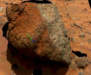
Example of a point measurement displayed in the 3D window
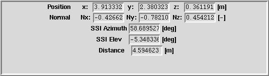
Display of the point measurement
Position X,Y,Z: 3D coordinates with respect to origin (Setting -> Reference
Frame to show origin)
Normal Nx,Ny,Nz: Surface normals at this location
SSI Azimuth/Elevation: Azimuth/Elevation with respect to SSI camera
Distance: distance from origin.
Note that in the Options window, whenever the checkbox "Log to:" is checked,
VIZ will log the measurement. The same feature is available for Distance,
Surface and Volume measurement.
Distance
measurement
Press the distance measurement button
Move the mouse to the 1st point and press the left mouse button
Move the mouse to the 2nd point and press the left mouse button
Example of a distance measurement displayed in the 3D window
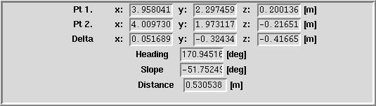
Display of the distance measurement
Pt 1, Pt 2: XYZ coordinates of the tie points
Delta: coordinates of vector Pt1->Pt2 (useful for instance if you want
to know only the vertical distance between Pt1 and Pt2).
Heading: angle between axis X and vector Pt1->Pt2
Slope: angle between horizontal plane XY and vector Pt1->Pt2
Distance: length of the vector (distance between Pt1 and Pt2)
Note that since there might be objects between Pt1 and Pt2, the red line
might be occluded.
Surface
measurement
Press the surface measurement button
Draw a polyline in the 3D window
Example of a surface measurement displayed in the 3D window
Display of a surface measurement
# of Pts: number of tie points forming the polyline
Perimeter: sum of all segment length of the polyline
Surface: surface formed by the polyline (3D or projection ???)
Volume
measurement
In order to measure a volume, you need to tell VIZ what the ground elevation
is. This way, if there's a hole in the terrain, VIZ will assume the terrain
is at ground level. Once you have specified the ground elevation and the
polyline defining which part of the terrain you want to measure the volume
from, VIZ will cast vertical rays down to the surface and place a green
dot marker where each ray intersected with the terrain. Note that the volume
might be incorrect if the defined volume is concave (ie there's an overcast
above the terrain, like in Yogi).
Each green dot has an elevation above the ground and define a small
dV (dV = spacing^2 * elevation). The volume is the sum of all dV. The volume
is defined by the volume of the surface enclosed in the polyline and a
horizontal plane at ground elevation.
Use the Point measurement to measure the local ground elevation (write
down the Z coordinate)
Press the Volume measurement button
Enter the Ground elevation value
Enter the Spacing (spacing is the linear horizontal distance (along X or
Y) between each ray: it basically defines the sampling rate of the surface).
Draw a polyline around the area you want to measure
Example of a volume measurement displayed in the 3D window
Display of a volume measurement
# of points: number of points defining the polyline
# of samples: number of rays cast onto the surface
Volume: volume defined by enclosed surface and horizontal plane at ground
elevation
Press Setting->Remove volume markers to revome the green dot indicators.
Cross-section
Similarly to the Volume measurement tool, the cross-section tool vertically
cast rays down to the terrain. The intersection of the ray with the terrain
are marked by a blue mark. You can specify the space between each ray in
the Spacing entry.
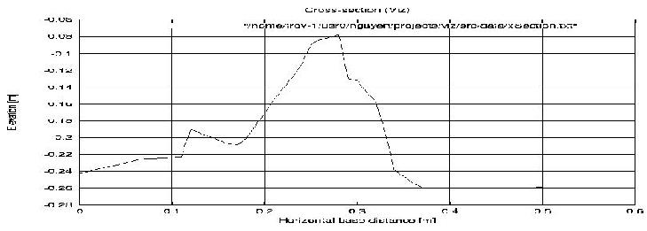
The cross-section tool outputs a text file with the elevation with respect
to horizontal distance of each of the blue mark. It also saves and displays
a Postscript plot of that file.
Press the cross-section button
Draw a polyline (can be a broken polyline)
Example of a cross-section displayed in the 3D window
Display of a cross-section measurement
Note that you can remove the blue marks by clicking on Setting->"Remove
Xsection markers"
Isoplane
The Isoplane is a semi-transparent plane of constant elevation. By moving
the plane up and down, you can hide and show features on the terrain and
highlight its topology. In the image below, what's blue is underneath the
isoplane, and what's orange is above, thus showing that the terrain around
the rock Yogi is slopy.
By default, the plane is horizontal, but the "Isoplane" option panel
allows you to change its orientation (Theta, Phi), size and transparency
(Alpha).
You can also hide or show it.
The isoplane displayed in the 3D
Selection
If you click on the Selection button, you will be able to select any object
in the scene by pointing and clicking on it. The selected object should
appear highlighted.
For the Mars Polar Lander dataset, if you selected a patch on the terrain,
the "Get Web Page" button will open in netscape a page corresponding to
the original image.
If a Marker has been selected, the Marker Edit window is automatically
called.
Press again on the Selection Button to unhighlight the selected object.
 Distance
measurement
Distance
measurement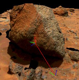
 Surface
measurement
Surface
measurement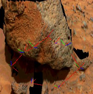

 Volume
measurement
Volume
measurement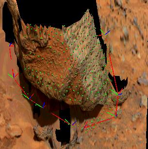

 Cross-section
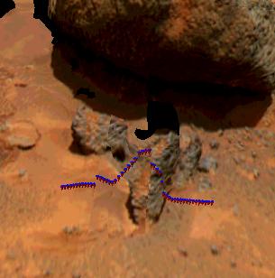
 Isoplane
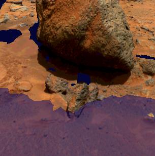
 Selection